Roof And Truss Point Loads Supported

Roof Steel Truss Supported On Masonry Wall With Concrete Chainage Beam Steel Trusses Masonry Wall Steel Roofing

Roof Steel Truss Column Overhang Connection Detail Steel Trusses Steel Roofing Roof Trusses
Roof Trusses Best Way To Frame

Metal Stud Roof Truss Design And Villa Karsinnat Roof Truss Design Roof Trusses Steel Trusses

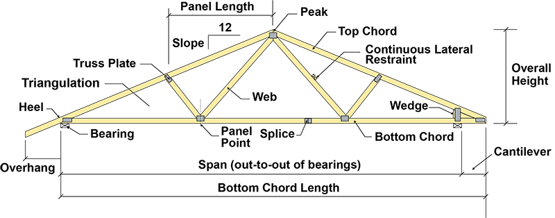
Different Types Of Roof Roof Trusses And Their Components Engineering Basic Roof Trusses Roof Truss Design Roof

Roof Truss Types Components Advantages In 2020 Roof Truss Design Roof Trusses Roof Architecture

Some trusses contain central support while others lack it.
Roof and truss point loads supported. How to order roof trusses successfully. In this situation the walls of a finished attic space or room would go with the roof line. Loads on roof trusses. This is a very god assumption because as we have seen earlier while introducing a truss triangle with pin joint the load is transferred on to other member of the trusses so that forces remain essentially collinear with the member.
Factors affecting the need for central support include the size and type of truss used in a construction project. Extra support for the trusses can be made by placing a 2 by 4 inch piece of lumber from each truss on one side to the truss on the other side high enough to provide head room but low enough to provide support for the trusses. These consist of weights of trusses roof coverings purlins and bracings. While this article focuses on configurations we also have a very cool set of illustrations showcasing the different parts anatomy of roof trusses.
A fixed node will provide support in both directions down the length of the roof truss members often called the x and y directions. This means that one is a fixed node and the other is a rolling node. It s crucial that we factor in the proper truss load. If dead loads must be hung from trusses then extra support can be provided by installing support beams perpendicular to the trusses reducing the span of the bottom chords and increasing their ability to carry the weight load.
The amount of weight a truss needs to support per square foot is important. Compromised trusses can lead to severe structural problems such as bowing exterior walls sagging ridge lines and roof collapse. If the middle line of the members of a truss meet at a point that point is taken as a pin joint. For instance determining whether roof trusses need support in the center entails numerous considerations rather than a simple answer.
Roofs are under a lot of pressure. For such conditions the scissors truss the curb truss the shed truss the three hinged arched truss the hammer beam truss are also used. Load limits on the roof of a building. Usually the dead load on the truss is expressed as the load per unit horizontal area.
In order to stay intact and in place a roof must be able to resist loads both permanent and temporary that are pushing.

Open Web Steel Joists Closely Spaced Shop Fabricated Standardized Lightweight Steel Trusses That Span B Roof Truss Design Metal Roofing Prices Steel Trusses

Medeek Design Inc Truss Gallery Gambrel Roof Gambrel Roof Trusses Roof Truss Design

Sketch Of A Hammer Beam Roof Roof Truss Design Roof Construction Timber Frame Joinery
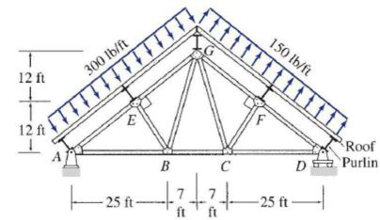
4 30 And 4 31 Determine The Force In Each Member Of The Roof Truss Shown The Roof Is Simply Supported On Purlins Which In Turn Are Attached To The Joints Of The Top

Medeek Design Inc Truss Gallery Roof Truss Design Attic Truss Roof Trusses

Best Truss Bridge Design Bridge Design Truss Bridge Bridge Engineering

Truss Bridge Tension And Compression Truss Bridge Tension And Compression Analysis Physics Sta Civil Engineering Design Structural Engineering Bridge Design

Pin On Engenharia

What Kind Of Trusses To Use For Different Roof Ceiling Shapes Gambrel Roof Gambrel Roof Trusses Roof Truss Design

Pin On Locations Interiors

Roof Trusses Civil Engineering

Pin On New
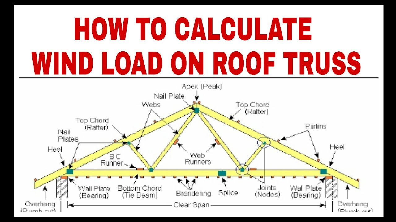
Roof Truss Dead Load Live Load Wind Load Calculations Part 1 Youtube

